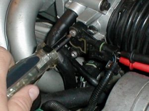
Before continuing, you should have cleaned your IAC valve and adjusted your minimum air (or idle speed). Otherwise your throttle response may suffer and have poor idle. This is to ensure that the following adjustment works in conjunction with the other settings in getting an accurate result. Ever hear of adjusting your TPS, but don’t really know how or what it is? We’ve seen numerous how to’s out there that explain how to hook up your voltmeter and what not, but don’t know where to adjust to or even how to adjust it? We hope to ease to confusion here. What you will need is a torx screwdriver (T-25) to make adjustments and a voltmeter (digital preferred). If you are lucky enough to have a scanner (Auto XRay Scanner) and know how to incorporate this into this adjustment, by all means … go right ahead! Some may also elect on making jumper wires to go from the TPS connector to the TPS and attach the voltmeter, via clip-leads. As long as the connector is attached to the TPS during measurement. The following is how I did the adjustment, no need for jumper wires and no need for a scanner. Just a regular old digital voltmeter you can pick up at Wal*Mart for $20. The one I used is kind of pricey, but they function the same. Go ahead and turn your ignition to ON. Do NOT start the engine. This works best on a fully charged battery. Insert your voltmeter leads in contacts 1 & 2, negative on top, positive in the middle. (Bottom contact 3 is not used during this procedure).
Set your voltmeter to DC (20VDC if not auto) and read the voltage in the idle position. If you’re not getting a reading, wiggle around the leads a bit and see if that helps. Sometimes I get a good connection, other times I have to wiggle the leads. If still no voltage reading, make sure your ignition is turned ON and you have voltage from the battery.
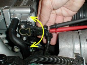
My voltage was reading 4.39VDC so I loosened the top and bottom torx screws just enough to where I can move the sensor sort of clockwise and/or counter-clockwise to adjust and to where it won’t move on you when you let go to tighten the screws.
Once you get the proper setting (0.540VDC +/- 0.075VDC or 0.465VDC to 0.615VDC for MAF equipped cars, 0.710VDC +/- 0.050VDC or 0.660VDC to 0.760VDC for non-MAF or Speed Density equipped cars), tighten the sensor up, then recheck to make sure you didn’t move it out of range. I have found that the closer you have it to the middle setting (0.540VDC for MAF or 0.710 for SD), the better your throttle response will be.
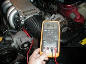
As you can see above, mine was dead on during adjustment. Keep in mind that any small movement of the throttle will cause different readings, but should be close to what you set it to. Sometimes you may get a slightly different reading other than what you set it to, but as long as it’s close. A perfect adjustment won’t stick, but is damn close. Now, while you have your voltmeter connected and reading. Slowly move the throttle to WOT (Wide Open Throttle) and carefully monitor the voltage. It should go steadily up and not “jump” around. If it does jump around or is not a smooth definite increase in voltage, you may have a faulty TPS. At WOT you should be over 4.000VDC. This tells the ECM you’re at WOT. Hint: Don’t feel too bad if you can’t get to over 4.000VDC. I could only get to 3.780VDC at WOT. I will look into that later and see if maybe I may have something going on there. Because my previous voltage was over 0.100VDC off, when adjusted, I noticed a much better, solid throttle response. Of course, I’m sure that the airfoil and plenum boring may have helped as well, but the TPS should not be overlooked! -Allan Reinike